In this section of the tutorial, configuration of RS232 ASCII streaming devices is explained
Examples of RS232 ASCII streaming devices:
- Invos NIRS
- Sophysa Pressio
- Hamamatsu NIRO
(Incidentally the first two already have custom modules created, thus not needing this type of configuration, but the principle still stands.)
Every device in this category is configured in a similar way in ICM+. There will however be some device specific configurations that will differ depending on the device.
The following video will demonstrate the all the steps needed to configure an INVOS device in ICM+:
Video subtitles:
- Click on the Signal sources button
- Select the ‘RS232 ASCII streaming Devices’ tab
- Click on the button Add
- Add a name to the device
- INVOS in this case
- Click on the settings button
- Choose the COM port at which the device is connected
- Choose the baud rate the device uses
- Fill in the rest of the parameters according to the device specifications
- Click on OK to lock in the changes
- Click the OK button
- Continue configuring the device specific parameters provided to you
- Click on Test Serial, Data should start appearing on the text box
- Click on Test Packet, now one single message should be presented on the text box
- At this point we need to identify the position on the message the values we are interested are in.
- Position 10 in this example
- Click test parse to see a list of values from the message
- Here we can verify the value of interest is indeed in position 10
- Click on OK to save the device
- Click on Add to add a new signal to the list
- Add a name to the Signal, rSO2 in this case
- Add the signal units and the valid ranges
- Add the position in the message where the signal is located, 10 in this case
- Click on Start and you should see a preview of the signal
- Click on OK to add the signal to the list
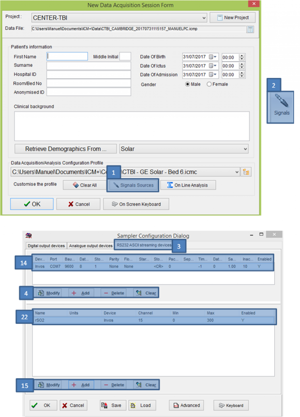
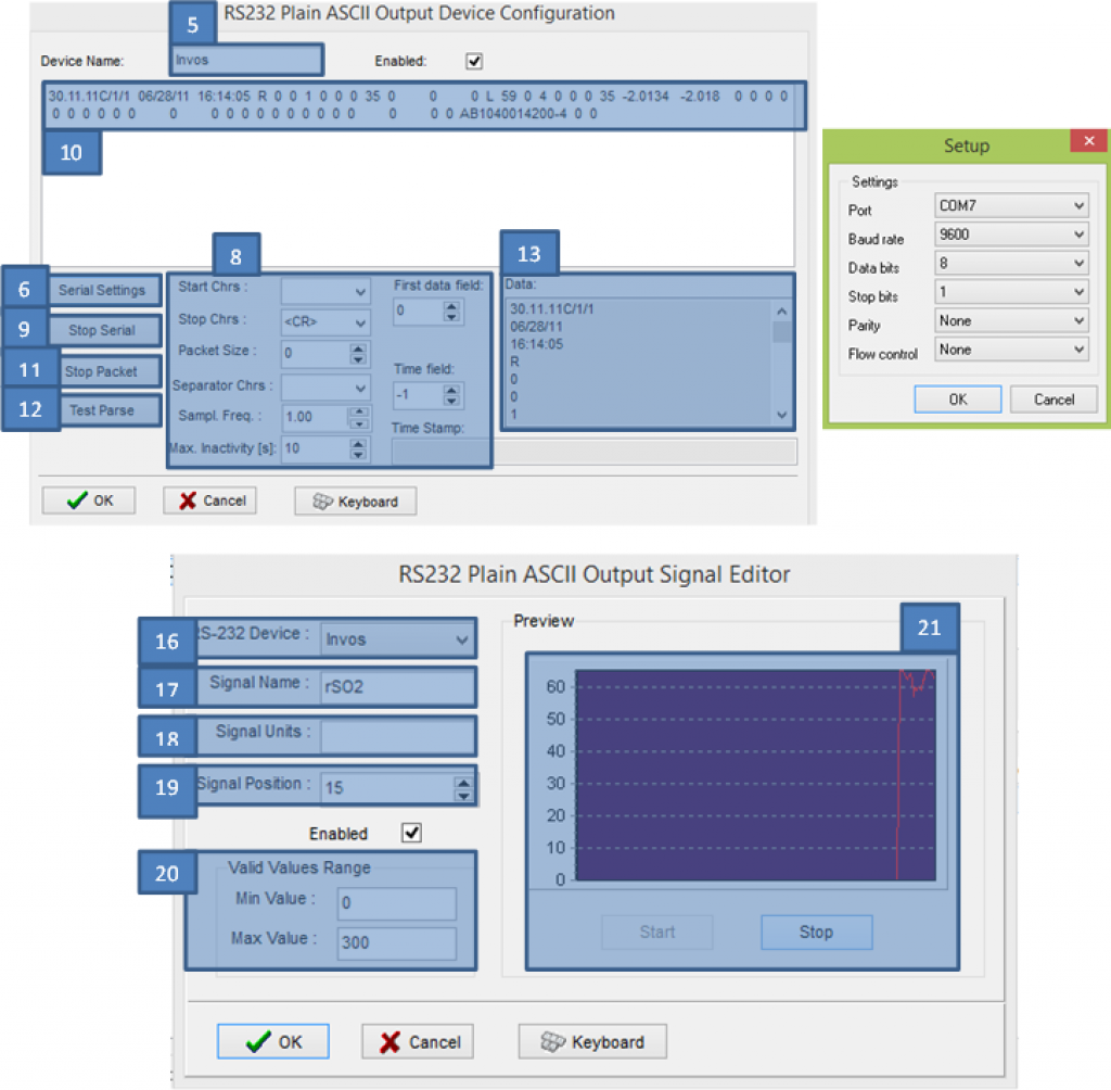
This will open the ‘Sampler Configuration Dialog’ and here click on the tab for RS232 ASCII streaming devices (3), in this window will be presented all the devices that communicate in this way (14). The buttons in (4) are used to modify any configured devices or add new devices. After you click the ‘Add’ button (4) the ‘RS232 Plain ASCII Output Device Configuration’ dialog appears. Here you must add a name to the device being configured (5). After this you must configure the Serial port settings (6). In here you will define the actual port the device is connected to, the baud rate at which it is transmitting, the number of data bits that should be expected, the number of Stop bits and others (7). These values should be provided to you be us or by the devices manufacturer.
After configuring the Serial ports, we will have to configure the message parser (8). These values should also be provided to you by us or by the device manufacturer. In the case of the example, there are no Start Char (character that defines the beginning of a message), The stop char (Character that terminates a message) is the ‘Carriage return’ CR, the Packet Size will be the number of bits a message can have (in this case 0 is the default value for ‘any number of characters) the separator char is what defines the separation of fields in the message (in the case of this example the separator is a space ‘#20’. The sampling frequency is the rate at which the data is arriving from the device (measured in samples/second), the Max inactivity is the amount of time ICM+ will wait until it decrees that the device is disconnected. The ‘First data field’ is where you define at which point in the message, the first data element is located. The ‘Time Field’ is where you define the field the will contain the time of sample collection (in this example -1 is the default value for no timestamp field.
After everything is configured, the serial connection can be tested (9) and you should start seeing messages appearing in the screen (10). After you click on Test Packet (11) the application will try to isolate messages based on the configurations of (8) and if everything is well you should only see one message at a time appearing in the screen. By clicking the Test Parse (12) you will test the rest of the configurations of (8) and you should see a list of data Fields as in (13). Here you should count the position of the data fields that are of interest (first element is a 0) for the next part of the configuration. Click ok in to get out of that window.
You should now see another device in the device list In (14). After this click on the ‘Add’ button in (15) to start configuring signals to be collected and stored by the application. In (16) the device of origin of the signal can be selected, you should then name the signal (17) and attribute Units to it (if applicable) (18). You will then have to define the position of the signal in the message from the device (19) and the Valid Values Range in (20) (these will automatically ignore data above or below the stipulated values). In order to test the configured signal, click on the ‘Start’ button (21). After you confirm this window, you should see a new signal at the end of the list (22).
These configurations only need to be performed once, as they can be saved in ICM+ configuration profiles. An example of the section of the configuration profile that contains this information is presented bellow.
